Talk About Industry Articles

Find All Information About Industry Equipment & Experts

Talk About Industry Articles

Find All Information About Industry Equipment & Experts

۲۴ مطلب در تیر ۱۴۰۰ ثبت شده است

  • ۰
  • ۰

Boiler & Heat Exchanger

 In this article, we will talk about boilers and heat exchangers. Then we will examine one of the types of boilers.

Heat Exchanger

Definition: A heat exchanger is a system used to transfer heat between two or more fluids. Heat exchangers are used in both cooling and heating processes.

Another example is the heat sink, which is a passive heat exchanger that transfers the heat generated by an electronic or a mechanical device to a fluid medium, often air or a liquid coolant.

U-tube heat exchanger is a form of tube and shell heat exchanger that is used in petroleum and chemical machinery. The tube box, casing, and tube buddle are the key components of a u-tube heat exchanger. Furthermore, drying is simple following the hydro test of the u-tube heat exchanger. read more


Boiler

Definition: A boiler is a closed vessel in which fluid (generally water) is heated. The fluid does not necessarily boil. The heated or vaporized fluid exits the boiler for use in various processes or heating applications, including water heating, central heating, boiler-based power generation, cooking, and sanitation.

System boiler: A system boiler, like a traditional boiler, requires a hot water storage tank but not a water container. This is due to the fact that the system’s main components, such as the expansion vessel and pump, are pre-assembled. System boilers are typically easier to maintain because they do not need a tank, eliminating the risk of leaks or damage. A machine boiler can be appropriate if you don’t have enough space for a tank but have several bathrooms.

  • Alex Alexian
  • ۰
  • ۰

 Many heat exchangers are U-shaped to maximize tube surface and heat exchange in a confined room. A u-tube heat exchanger or let’s say a u-tube configuration also makes it simple to enter the package.

There are three primary classifications of heat exchangers according to their flow arrangement. In parallel-flow heat exchangers, the two fluids enter the exchanger at the same end, and travel in parallel to one another to the other side.

One of the most significant advantages of the straight tube heat exchanger is its simplicity. Straight tube exchanger is also common because of its flexibility. Straight tube exchanger allows for pure countercurrent flow within the exchanger without the need for a second one to be connected in series to the first. 


About System Boiler

In a fossil fuel power plant using a steam cycle for power generation, the primary heat source will be the combustion of coal, oil, or natural gas. In some cases byproduct fuel such as the carbon monoxide-rich off-gasses of a coke battery can be burned to heat a boiler; biofuels such as bagasse, where economically available, can also be used. In a nuclear power plant, boilers called steam generators are heated by the heat produced by nuclear fission. 

Several factors should be taken into account when choosing the correct boiler. If you’re replacing an old boiler in your new home or buying one for the first time, the following considerations will help you choose the best boiler for your needs. It’s important to remember that only a professional and knowledgeable gas engineer will advise you on the appropriate boiler for your home and requirements.


References:


https://en.wikipedia.org/wiki/Heat_exchanger
https://www.siemens.com/global/en.html

https://www.linquip.com/blog/what-is-u-tube-heat-exchanger/

https://www.britannica.com/

https://www.linquip.com/blog/the-10-best-system-boilers-of-2021-2/

https://www.ethosenergygroup.com/

  • Alex Alexian
  • ۰
  • ۰

In this article, we are going to talk about Surface Heat Exchanger and Plate Heat Exchanger. First, we give a brief definition of both, then we examine the types and components of each and how each works. Read this article to the end. 

Plate Heat Exchanger

As defined by Wikipedia: A plate heat exchanger is a type of heat exchanger that uses metal plates to transfer heat between two fluids. This has a major advantage over a conventional heat exchanger in that the fluids are exposed to a much larger surface area because the fluids are spread out over the plates. This facilitates the transfer of heat, and greatly increases the speed of the temperature change. A plate exchanger consists of a series of parallel plates that are placed one above the other so as to allow the formation of a series of channels for fluids to flow between them. Read more

Types of Plate Heat Exchanger

Double pipe heat exchangers are the simplest exchangers used in industries. On one hand, these heat exchangers are cheap for both design and maintenance, making them a good choice for small industries. On the other hand, their low efficiency coupled with the high space occupied in large scales has led modern industries to use more efficient heat exchangers like shell and tube or plate. Different types of plate heat exchanger have many potential applications. This includes pasteurizers, beverage processing, connectors between chillers, boilers, and cooling towers, and other process engineering applications.

working principle of plate heat exchanger

A plate heat exchanger comprises a series of parallel plates placed one above the other to form a series of channels for the flow of fluids between them. The space between two neighboring plates forms the channel through which the fluid flows. 

scraped surface heat exchanger

Another type of heat exchanger is called "scraped surface heat exchanger". This is mainly used for heating or cooling with high-viscosity products, crystallization processes, evaporation and high-fouling applications. Long running times are achieved due to the continuous scraping of the surface, thus avoiding fouling and achieving a sustainable heat transfer rate during the process.

Scraped surface heat exchanger is made up of a jacketed cylinder with a spinning dasher that holds rows of scraper blades. When the product is being pumped into the cylinder, the heating or cooling medium is being circulated between the cylinder and the jacket. Steam, vapor, or a refrigerant such as ammonia or freon may be used as the medium.

  • Alex Alexian
  • ۰
  • ۰

A plate heat exchanger is used to transfer heat energy from one fluid to another. These fluids never encounter each other due to being separated by the heat exchanger.

A plate heat exchanger is a type of heat exchanger that uses metal plates to transfer heat between two fluids. This has a major advantage over a conventional heat exchanger in that the fluids are exposed to a much larger surface area because the fluids are spread out over the plates.

Different types of plate heat exchanger have many potential applications. This includes pasteurizers, beverage processing, connectors between chillers, boilers, and cooling towers, and other process engineering applications. The plates are often spaced by rubber sealing gaskets which are cemented into a section around the edge of the plates. The plates are pressed to form troughs at right angles to the direction of flow of the liquid which runs through the channels in the heat exchanger. 


The corrugation on the plates drives the fluid on a tortuous path, creating a distance from 1 to 5 millimeters between two adjacent plates.

The fluids can pass through the channels in series (a less common solution) or parallel by making counter-flow configurations.

A heat exchanger is a system used to transfer heat between two or more fluids. Heat exchangers are used in both cooling and heating processes.

Heat transfer to highly viscous or sticky materials is needed in certain applications. A scraped surface heat exchanger is the best option for providing efficient heat transfer in such applications because the scraping blades prevent the product from accumulating on the internal surfaces.


Reference:

https://en.wikipedia.org/wiki/Heat_exchanger#Dynamic_scraped_surface_heat_exchanger

https://www.linquip.com/blog/plate-heat-exchanger/

https://www.youtube.com/

https://www.linquip.com/blog/types-of-plate-heat-exchanger/

https://www.britannica.com/

https://www.linquip.com/blog/working-principle-plate-heat-exchanger/

https://www.kawasaki.com/

https://www.linquip.com/blog/scraped-surface-heat-exchanger/

  • Alex Alexian
  • ۰
  • ۰

 In this post, we want to talk about Permanent Magnet Synchronous Motors and Capacitor Start Induction Motor. After introducing and reviewing each, we will examine the difference between motor and engine.

Permanent Magnet Synchronous Motors

First, we define the synchronous motor. A synchronous electric motor is an AC motor in which, at steady state, the rotation of the shaft is synchronized with the frequency of the supply current; the rotation period is exactly equal to an integral number of AC cycles. 

The Permanent Magnet Synchronous Motor (PMSM) is an AC synchronous motor whose field excitation is provided by permanent magnets. The permanent magnet synchronous motors are very efficient, brushless, very fast, safe, and give a high dynamic performance. Due to their advantages, permanent synchronous motors have many applications and find use in several fields.

Permanent Magnet Synchronous Motor (PMSM) is brushless and has very high reliability and efficiency. Due to its permanent magnet rotor, it also has a high torque with a small frame size and no rotor current. 


Capacitor Start Induction Motor

motor capacitor, such as a start capacitor or run capacitor (including a dual run capacitor)is an electrical capacitor that alters the current to one or more windings of a single-phase alternating-current induction motor to create a rotating magnetic field.

A Capacitor Start Motors is a single phase Induction Motor that employs a capacitor in the auxiliary winding circuit to produce a greater phase difference between the current in the main and the auxiliary windings. The capacitor start motor has a cage rotor and has two windings on the stator. They are known as the main winding and the auxiliary or the starting winding.


Differences Between Motor and Engine

By Wikipedia definition:An engine or motor is a machine designed to convert one form of energy into mechanical energy.

But what is the difference between motor and engine?

Motor” is originated in the Classical Latin movere, “to move.” It first mentioned the propulsive force, and later, to the person or system that moved something or caused the movement. 

“Engine” is from the Latin root: mental powers, character, intellect, talent, or cleverness. In its journey through the French language and into English, the term came to mean contrivance, ingenuity, and trick or malice. “

  • Alex Alexian
  • ۰
  • ۰

We are going to talk about Differences Between Motor and Engine. We will first define the engine.

 A motor capacitor, such as a start capacitor or run capacitor  is an electrical capacitor that alters the current to one or more windings of a single-phase alternating-current induction motor to create a rotating magnetic field.

“Motor” is originated in the Classical Latin movere, “to move.” It first mentioned the propulsive force, and later, to the person or system that moved something or caused the movement.


The word engine derives from Old French engin, from the Latin ingenium–the root of the word ingenious. Pre-industrial weapons of war, such as catapults, trebuchets and battering rams, were called siege engines, and knowledge of how to construct them was often treated as a military secret. The word gin, as in cotton gin, is short for engine. “Engine” is from the Latin root: mental powers, character, intellect, talent, or cleverness. 

A Capacitor Start Motors is a single phase Induction Motor that employs a capacitor in the auxiliary winding circuit to produce a greater phase difference between the current in the main and the auxiliary windings.

The permanent magnet synchronous motors working principle is similar to the synchronous motor. The principle of operation is based on the interaction of the rotating magnetic field of the stator and the constant magnetic field of the rotor. It depends on the rotating magnetic field that generates electromotive force at synchronous speed. 

You can get more information about engines by reading the following links.


References:

https://www.linquip.com/blog/what-is-capacitor-start-induction-motor/

https://en.wikipedia.org/wiki/Motor_capacitor

https://www.energy.gov/

https://www.linquip.com/blog/differences-between-motor-and-engine/

https://www.gm.com/

https://www.linquip.com/blog/permanent-magnet-synchronous-motors/

  • Alex Alexian
  • ۰
  • ۰

 In previous articles, we talked about the types of engines. In this article, we will introduce and review Single-Phase Induction Motor, Commutator Motors, and also Types of Induction Motor. Join us and read this article.

Induction motor

An induction motor or asynchronous motor is an AC electric motor in which the electric current in the rotor needed to produce torque is obtained by electromagnetic induction from the magnetic field of the stator winding.

There are mainly two types of induction motor. This classification is based on what power supply induction motors are fed with. Single-phase induction motors and three-phase induction motors are the two main types of induction motors. 

One of the types of induction motors is single-phase induction motor. The two main components of the single-phase induction motor are the stator and rotor. As you may know and  perceive from the name, the Stator is the stationary part of this motor. On the other hand, the rotor is the rotating component of the motor. the single-phase alternating supply reaches to the stator winding. more information


Commutator Motors

An electric motor is an electrical machine that converts electrical energy into mechanical energy. Most electric motors operate through the interaction between the motor's magnetic field and electric current in a wire winding to generate force in the form of torque applied on the motor's shaft. Electric motors can be powered by direct current (DC) sources, such as from batteries, or rectifiers, or by alternating current (AC) sources, such as a power grid, inverters or electrical generators. One of the types of electric motors is Commutator Motors.

As you may know, The operating principle of DC motors is on the basis of the mutual interaction between the magnetic field of an armature rotating and the magnetic field of a fixed stator. 

  • Alex Alexian
  • ۰
  • ۰

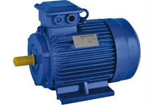
 The motor is one of the most important parts of electrical equipment. There are different types of engines and we have talked about them in previous articles. In this article, we will talk about Induction Motor and examine one of its types.

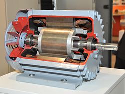
An induction motor or asynchronous motor is an AC electric motor in which the electric current in the rotor needed to produce torque is obtained by electromagnetic induction from the magnetic field of the stator winding. An induction motor can therefore be made without electrical connections to the rotor. An induction motor's rotor can be either wound type or squirrel-cage type.

based on the construction and starting method, the single-phase induction motor is categorized into the four types of Split Phase, Capacitor Start, Capacitor Start Capacitor Run, and Shaded Pole. In the following sections, we will elaborate on each of these types of single-phase induction motors.


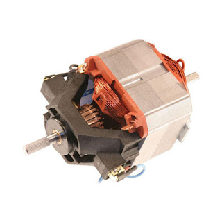
A commutator is a rotary electrical switch in some motors that supplies current to the rotor. It consists of a cylinder composed of multiple metal contact segments on the rotating armature of the machine. Two or more electrical contacts called "brushes" made of a soft conductive material like carbon press against the commutator, making sliding contact with successive segments of the commutator as it rotates, supplying the current to the rotor. The windings on the rotor are connected to the commutator segments.

A commutator itself is a split rotary ring, typically made of copper, with each segment of the ring attached to each end of the armature coil that is used in some types of electric motors and electrical generators whose job is to periodically reverse the current direction between the rotor and the external circuit.


References:

https://www.linquip.com/blog/types-of-induction-motor/

https://en.wikipedia.org/wiki/Induction_motor

https://www.gm.com/

https://www.linquip.com/blog/single-phase-induction-motor/

https://www.ethosenergygroup.com/

https://www.linquip.com/blog/commutator-motors/

  • Alex Alexian
  • ۰
  • ۰

In this article, we will introduce several types of compressors and explain the differences between them. Stay with us.

First we introduce the Centrifugal Compressor and then we review the Centrifugal Compressor Work. We will also introduce the types of Centrifugal Compressor.

A compressor is a mechanical device that increases the pressure of a gas by reducing its volume. An air compressor is a specific type of gas compressor.

Compressors are similar to pumps: both increase the pressure on a fluid and both can transport the fluid through a pipe. 

Centrifugal compressors, sometimes called radial compressors, are a sub-class of dynamic axisymmetric work-absorbing turbomachinery.

Centrifugal compressors are considered as a dynamic compressor type that has a radial design.  These compressors work with a constant pressure unlike the ones working at a constant flow. Plus, any changes in the external conditions affect the performance.

Types of Centrifugal Compressor

Centrifugal Compressor generally consists of 2 categories:

  • Single Stage Compressor
  • Multi-Stage Compressor

Single-stage compressors are among the popular types of centrifugal compressors available on the market. This type has a single impeller for directing the air or other gases for its specific purpose. The single-stage compressor also contains a diffuser and connected guide vanes.

But what is axial compressor vs centrifugal compressor?

An axial compressor is a gas compressor that can continuously pressurize gases. It is a rotating, airfoil-based compressor in which the gas or working fluid principally flows parallel to the axis of rotation, or axially. 

Some of the differences between them are:


  • Centrifugal compressors are easier to design and manufacture compared to axial compressors.
  • Contrary to centrifugal compressors, axial flow compressors do not change the direction of the gas.

radial compressor

radial compressors is actually another name for Centrifugal compressors. A radial compressor contains radial blades on its rotating impeller and the air is drawn into the center of this unit. The centrifugal force pushed the air into the center. The air’s radial movement inside these compressors will raise the pressure, resulting in the generation of kinetic energy.


rotary compressor vs reciprocating compressor

A reciprocating compressor or piston compressor is a positive-displacement compressor that uses pistons driven by a crankshaft to deliver gases at high pressure.

  • Size
  1. The size of the rotary compressors is smaller than the reciprocating compressor for the same discharge.
  2. The size of the reciprocating compressor is bulky and larger than the rotary compressor for the same discharge. 

read more

  • Alex Alexian
  • ۰
  • ۰

 Centrifugal Compressor is one of the types of compressors. In this post, we talked about how it works, its types, and comparing it with several other compressors.

The radial compressor is also called a centrifugal compressor. This kind of dynamic compressor has a radial design. They operate at constant pressure and any changes in the external conditions will affect the performance of these compressors.

Centrifugal compressors, sometimes called radial compressors, are a sub-class of dynamic axisymmetric work-absorbing turbomachinery.

They achieve a pressure rise by adding kinetic energy/velocity to a continuous flow of fluid through the rotor or impeller.  


Types of  Centrifugal Compressor


  • Multi-Stage Compressor


Multi-stage compressors are among different types of centrifugal compressors. As the name suggests, this compressor has been designed to pass the gas through multiple stages for diverse purposes. Multi-stage compressors are used when a single-stage compressor can’t keep up with the desired pressure requirements. This is because a single-stage compressor, as mentioned above, has only one impeller.

The simple explanation regarding “how does a centrifugal compressor work?” would be that they transform the velocity and the kinetic energy in the diffuser into the pressure energy.

There is a rotating impeller inside centrifugal compressors that has radial blades and the center of this impeller receives the air that is pushed by centrifugal force toward the center.

Differences Between Axial Compressor & Centrifugal Compressor:


  • Axial compressors are very expensive while centrifugal compressors are cheaper and have a wider operating range.
  • The mass flow rate in centrifugal compressors is less than 15 Kg/s and in the axial compressors is very large (more than 100 Kg/s).
  • Axial compressors operate more efficiently (about 94%) than centrifugal compressors (about 87%).

Differences Between Rotary & Reciprocating Compressors

  • Efficiency
  1. The efficiency of the rotary compressor is nearly 100%.
  2. The efficiency of the reciprocating compressor is less than 100%.


References:


https://www.linquip.com/blog/the-differences-between-rotary-reciprocating-compressors/

https://en.wikipedia.org/wiki/Centrifugal_compressor

https://www.linquip.com/blog/radial-compressor/

https://www.energy.gov/

https://www.linquip.com/blog/differences-between-axial-compressor-centrifugal/

https://www.ethosenergygroup.com/

https://www.linquip.com/blog/how-does-centrifugal-compressor-work/

https://www.britannica.com/

https://www.linquip.com/blog/types-of-centrifugal-compressor/

  • Alex Alexian