Talk About Industry Articles

Find All Information About Industry Equipment & Experts

Talk About Industry Articles

Find All Information About Industry Equipment & Experts

  • ۰
  • ۰

 Turbines actually act as converters. They convert wind or sea energy into electrical energy and are considered as an alternative to non-renewable resources. There are different types of turbines, such as Impulse Turbine, wind turbine, etc.

Impulse Turbine

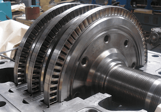
In these turbines, the static pressure inside the runner is constant, and the turbine runner is at atmospheric pressure. The runner spins in the air, and the fluid is sprayed to the blades through the nozzle to exchange energy with the turbine. A jet nozzle or a series of nozzles directs the high-speed flow to the blades, which are usually in the shape of buckets or cups. Therefore, only pressure changes occur in the nozzles.

In the case of steam turbines, such as would be used for marine applications or for land-based electricity generation, a Parsons-type reaction turbine would require approximately double the number of blade rows as a de Laval-type impulse turbine, for the same degree of thermal energy conversion.


Francis Turbine

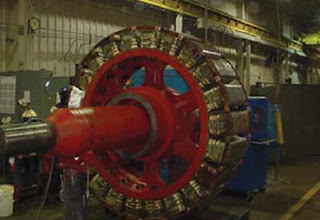
Francis turbines are primarily used for electrical power production. The power output of the electric generators generally ranges from just a few kilowatts up to 1000 MW, though mini-hydro installations may be lower. The best performance is seen when the head height is between 100–300 metres (330–980 ft).

rancis turbines are employed regularly in hydroelectric power plants. In these power plants, high-pressure water enters the turbine through the snail-shell casing (the volute). This movement decreases the water pressure as it curls through the tube; however, the water’s speed remains unchanged. Following the passing through the volute, the water flows through the guide vanes and is directed towards the runner’s blades at optimum angles.


Kaplan Turbine and Hydrokinetic Turbine


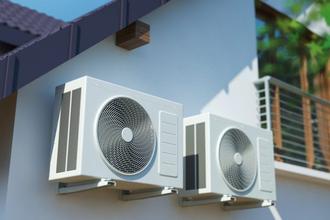
HK turbines have relatively simple designs without the need for a reservoir or spillway. Initial testing indicates the adverse environmental effects are minimal, and the simplicity of these designs results in low-cost installation and maintenance. Therefore, this simplicity makes these systems valuable in rural or remote areas. In the following figure, you can see the flow conditions of hydrokinetic turbines.


A Kaplan turbine is one kind of a propeller hydro turbine (particularly a reaction turbine) used in hydroelectric plants. Waterflow both in and out of Kaplan turbines through its rotational axis, which is called axial flow. The point that makes Kaplan turbines special is that the blades can change their demand to preserve maximum efficiency for various water flow rates. 


References:

https://www.linquip.com/blog/hydrokinetic-turbines/

https://www.youtube.com/

https://www.linquip.com/blog/kaplan-turbine/

https://www.energy.gov/

https://www.linquip.com/blog/what-is-francis-turbine/

https://www.ethosenergygroup.com/

https://www.linquip.com/blog/impulse-turbine-working-principle/

  • Alex Alexian
  • ۰
  • ۰

 linear potentiometer

A potentiometer is a three-terminal resistor with a sliding or rotating contact that forms an adjustable voltage divider If only two terminals are used, one end and the wiper, it acts as a variable resistor or rheostat.

Linear potentiometers have unique features to ensure long trouble-free life in the harshest of environments from motorsport to structural monitoring, from measuring linear position or displacement in a wide variety and broad range of manufacturing and process equipment. 


Series and parallel circuits

Two-terminal components and electrical networks can be connected in series or parallel. The resulting electrical network will have two terminals and can participate in a series or parallel topology. Whether a two-terminal "object" is an electrical component or an electrical network is a matter of perspective. This article will use "component" to refer to a two-terminal "object" that participates in the series/parallel networks. But what are the differences between series and parallel circuits?

Series and Parallel Circuit_ Close circuits have a complete path for current to flow in a loop. An open circuit does not have a closed-loop, which means that it’s not operative. A short circuit is a low-resistance path, usually made accidentally, that bypasses some parts of a circuit. A short circuit can occur when two bare wires in a circuit meet each other.  Read more


Forward Bias vs. Reverse Bias

In forward bias, the positive terminal of the battery is connected to the p-type material and the negative terminal is connected to the n-type material so that holes are injected into the p-type material and electrons into the n-type material. The electrons in the n-type material are called majority carriers on that side, but electrons that make it to the p-type side are called minority carriers. 

In reversed bias, there is a connection between the negative region and the positive terminal of the battery, and the positive region is joined to the negative terminal. The reverse potential boosts the strength of the potential barrier in this situation.

  • Alex Alexian
  • ۰
  • ۰

The measuring instrument called a potentiometer is essentially a voltage divider used for measuring electric potential (voltage); the component is an implementation of the same principle, hence its name.

To answer the question of what is linear potentiometer, first, let us see what are the different parts of this potentiometer. A linear taper potentiometer is usually made up of three pins that adjust to a flow of voltage, and produce a regulated voltage output relevant to its sliding components.


Parallel circuits are similar to the smaller blood veins that branch off from an artery and then join in a vessel to return blood to the heart. Now imagine two wires, each as an artery and a vein, that are connected to each other with some smaller wires. These smaller wires have the same voltages applied to them, but different amounts of current flow through them based on the individual wires’ resistance.

A circuit composed solely of components connected in series is known as a series circuit; likewise, one connected completely in parallel is known as a parallel circuit. Many circuits can be analyzed as combination of series and parallel circuits, along with other configurations.


In forward biasing, the external voltage supply is applied across the PN-junction diode. This voltage cuts the potential barrier and provides a low resistance way to the flow of current. The meaning of the forward bias is the connection of the positive region to the p-terminal of the supply, while the negative region is joined to the n-type of the device. To read more about these topics, you can use the references mentioned below.


References:

https://en.wikipedia.org/wiki/P%E2%80%93n_junction#Reverse_bias

https://www.linquip.com/blog/ultimate-guide-what-is-linear-potentiometer/

https://www.youtube.com/

https://www.linquip.com/blog/differences-between-forward-reverse-biasing/

https://en.wikipedia.org/wiki/Potentiometer

https://www.linquip.com/blog/differences-between-series-and-parallel-circuits/

  • Alex Alexian
  • ۰
  • ۰

cooling towers. A device for dissipating heat from processes such as water evaporation. In this article, we will introduce solutions for Increasing Cooling Tower Efficiency. Stay with us.

The U.S. Department of Energy (DOE) is proposing to provide funding to the State of Arizona to replace parts of the heating, ventilation, and air condition system that have reached their expected useful life with more energy-efficient equipment at the Arizona State Veterans’ Home in Phoenix, AZ. Specifically, the cooling towers, condenser pumps, air dirt separator, interconnecting piping with valves and fittings, and the controls would be replaced.


a cooling tower is a heat rejection device that rejects waste heat to the atmosphere through the cooling of a water stream to a lower temperature. Cooling towers may either use the evaporation of water to remove process heat and cool the working fluid to near the wet-bulb air temperature or, in the case of closed circuit dry cooling towers, rely solely on air to cool the working fluid to near the dry-bulb air temperature.


Recirculating cooling systems cool water by exposure to ambient air in either cooling towers or (less frequently) cooling ponds. Heat transfer with air occurs primarily through evaporation. As water evaporates, minerals and other impurities in the remaining coolant water become increasingly concentrated and must be removed by periodic “blowdown” cycles. Recirculating systems only withdraw makeup water to replace evaporative losses and maintain water quality. Recirculating cooling systems withdraw 20 – 80 times less water than once-through systems, but the percentage of water consumed is much greater. Once-through cooling systems consume about 4% of the water withdrawn, while recirculating systems consume 80% of the water withdrawn.


How To Increase Cooling Tower Efficiency?

Water used in the tower for the cooling process is cycled through the device a number of times before being discharged, and COC is a number that quantifies how many cycles there could be. It is considered the primary indicator of cooling tower efficiency.

Click here

You can also refer to the following resources to read about Cooling Tower Efficiency Calculation.

References:

https://en.wikipedia.org/wiki/Cooling_tower

https://www.linquip.com/blog/increasing-cooling-tower-efficiency-calculation/

https://www.energy.gov/nepa/downloads/cx-102001-pcs-21-003-azdvs-phoenix-home-cooling-tower-replacement

https://www.wartsila.com/energy/learn-more/technical-comparisons/combustion-engine-vs-gas-turbine-water-consumption

  • Alex Alexian
  • ۰
  • ۰

 In electricity generation, a generator is a device that converts motive power (mechanical energy) into electrical power for use in an external circuit. Sources of mechanical energy include steam turbines, gas turbines, water turbines, internal combustion engines, wind turbines and even hand cranks. The first electromagnetic generator, the Faraday disk, was invented in 1831 by British scientist Michael Faraday. Generators provide nearly all of the power for electric power grids.


This article is about the types of generators and the difference between DC and AC generators. If you have any questions about the Diff BW AC and DC Generator, read this article to the end.

AC generator is considered an electrical generator for converting mechanical energy into electrical energy. This energy is in the form of alternating current or alternative EMF.

DC generators convert mechanical energy into DC electricity which is short for Direct Current.


AC Generator vs Dc Generator

AC vs. DC: The Design and Mechanism The Diff BW AC and DC Generator in terms of design is that the AC generators’ current moves through the fixed coil. The flow of current remains in the opposite direction, with the help of a moving magnet. While in DC generators the coil moves in a fixed field and the current flow with this movement, so no fixed coils for DC generators.Read more

References:

https://www.linquip.com/blog/difference-between-ac-and-dc-generators/

https://www.energy.gov/articles/department-energy-announces-new-funding-opportunity-next-generation-dc-circuit-breakers

https://en.wikipedia.org/wiki/Electric_generator

  • Alex Alexian
  • ۰
  • ۰

Alternator and its types

 An alternator is an electrical generator that converts mechanical energy to electrical energy in the form of alternating current. For reasons of cost and simplicity, most alternators use a rotating magnetic field with a stationary armature. Occasionally, a linear alternator or a rotating armature with a stationary magnetic field is used. In principle, any AC electrical generator can be called an alternator, but usually the term refers to small rotating machines driven by automotive and other internal combustion engines.

You must have heard the name of the alternator by now. A device that converts mechanical energy into electrical energy. In this article, we will introduce and review the types of alternators. Stay with us.


Alternator Types

1.Diode Assembly DC, the current type used by car batteries, is converted into direct current by an alternator’s diode assembly (AC). The two-terminal diode assemblage works by allowing only one direction to flow the electricity generated by the stator.

2.Voltage Regulator To control the charging process, the voltage regulator controls the power supply from the alternator to the battery. Regulators are designed and work according to their specifications, with different functions. read more in this link


References:

https://www.linquip.com/blog/types-of-alternator-features-advantages/

https://en.wikipedia.org/wiki/Alternator

https://www.wartsila.com/energy/learn-more/references/utilities/kaloum-5-republic-of-guinea

https://www.energy.gov/eere/femp/federal-fleet-requirements-resource-center-alternative-fuel

  • Alex Alexian
  • ۰
  • ۰


The magnetic path is characterized by poles, locations at equal angles around the rotor at which the magnetic field lines pass from stator to rotor or vice versa. The stator (and rotor) are classified by the number of poles they have. Most arrangements use one field coil per pole. Some older or simpler arrangements use a single field coil with a pole at each end.


In this article, we will first introduce salient pole and cylindrical pole. We will explain the performance of each and at the end, we will examine the Difference between salient pole and cylindrical pole. Read this article.

The magnetic path is characterized by poles, locations at equal angles around the rotor at which the magnetic field lines pass from stator to rotor or vice versa. The stator (and rotor) are classified by the number of poles they have. Most arrangements use one field coil per pole. Some older or simpler arrangements use a single field coil with a pole at each end.salient pole rotors are large in diameter and shorter in length. They are typically used in lower speed electrical machines (100 RPM to 1500 RPM). Salient pole rotors normally require damper windings to avoid oscillations of rotors during operation. They are mostly used in hydropower plants.


salient pole vs cylindrical pole

The difference between salient pole and cylindrical pole is that the rotor of the cylindrical pole can run at a higher rotational speed, provided that the rotor is easily balanceable and the centrifugal force can be equally distributed. Click here References:

https://en.wikipedia.org/wiki/Field_coil

https://www.linquip.com/blog/difference-between-salient-pole-and-cylindrical-pole/

https://www.energy.gov/sites/prod/files/2021/01/f82/CX-022894.pdf


  • Alex Alexian
  • ۱
  • ۰

What is an alternator and a generator?


what is a generator? What parts does it consist of? Which component in the dc generator produces a magnetic field? What are Generator and Alternator Difference? Alternator and generator, the two main parts in electrical appliances. You have definitely heard their names many times and even seen them. Would you like to know more about them? In this post, we will introduce the alternator and generator, check the Difference Between Alternator and Generator. We will introduce the DC generator and examine the Parts of dc generator. So read this article to the end.

DC generator working is the conversion of mechanical energy into electricity. In electricity generation, a generator is a device that converts motive power (mechanical energy) into electrical power for use in an external circuit. Sources of mechanical energy include steam turbines, gas turbines, water turbines, internal combustion engines, wind turbines, and even hand cranks. The first electromagnetic generator, the Faraday disk, was invented in 1831 by British scientist Michael Faraday. Generators provide nearly all of the power for electric power grids.

An alternator is an electrical generator that converts mechanical energy to electrical energy in the form of alternating current. For reasons of cost and simplicity, most alternators use a rotating magnetic field with a stationary armature. Occasionally, a linear alternator or a rotating armature with a stationary magnetic field is used. In principle, any AC electrical generator can be called an alternator, but usually, the term refers to small rotating machines driven by automotive and other internal combustion engines. Based on several audits, Wärtsilä delivered a comprehensive solution to bring EDG’s power plant up to standard again; including a complete overhaul of engines and alternators. In addition, automation was upgraded and auxiliaries were modified and fine-tuned to suit the plant performance. Finally, the turbochargers were also upgraded with newer versions.

DC Generator Parts

Here we first say the name of the part of dc generator, then we will explain each one.

End Housings

Stator

Commutator

Shaft

Stator:

A direct-current (DC) generator consists of two main parts, a rotating section and a fixed one. Stator is the stationary part of this system that includes a core, stator winding, and the outer frame and houses the rotor (the rotating part) in its core. Read more

Alternator vs Generator

In this section, we examine the differences between alternator and generator.

As we already mentioned, an alternator only provides AC, but a generator generates both AC and DC. So, if you need DC, your only choice between alternator vs generator would be a generator. With every half rotation of the rotor, the current’s direction changes, causing the alternating current. The circuit’s ends are directly connected to the load for getting the produced AC. And when it comes to direct current or DC, these ends of the wire should be connected to the commutator which converts AC to DC. To read more about Generator Alternator Difference, you can refer to the resources introduced at the end of the article

Advantage of Alternator vs Generator

Alternators have some benefits over generators which are as follows.

Higher output

Lower weight and smaller size

Less maintenance

Read more here

References:


https://www.linquip.com/blog/parts-of-dc-generator-explanation-working/

https://en.wikipedia.org/wiki/Alternator

https://cdn.wartsila.com/docs/default-source/product-files/electric-propulsion-and-drives/brochure-o-ea-diesel-electric-propulsion-systems.pdf?sfvrsn=15f6ae45_6

https://www.energy.gov/articles/department-energy-announces-new-funding-opportunity-next-generation-dc-circuit-breakers

https://www.linquip.com/blog/alternator-vs-generator/

  • Alex Alexian
  • ۰
  • ۰

What is industrial gearbox?

An industrial gearbox is an enclosed system that transmits mechanical energy to a transmission unit. The system slows down the speed and torque of rotation. Industrial gearboxes are different from standard gearboxes, as the former needs a long, stable life and safety factor for most of the drives. To control speed and torque and convert it functionally, an industrial gearbox transmits mechanical power into a driving tool. In contrast to mass gearboxes, industrial gearboxes can handle multiple tasks at extremely high speeds over a long period. Read more here

What do you know about industrial gearbox? In this article, we intend to introduce the industrial gearbox and its applications. Read this article to the end.

A transmission is a machine in a power transmission system, which provides controlled application of power. Often the term 5-speed transmission refers simply to the gearbox, that uses gears and gear trains to provide speed and torque conversions from a rotating power source to another device.

The U.S. Department of Energy's National Renewable Energy Laboratory (NREL) has successfully demonstrated a new gearbox design developed by the Gearbox Reliability Collaborative (GRC), with a predicted lifetime 3.5 times greater than the previous, conventional design. NREL established the GRC in 2007 to address the failure of many wind turbine gearboxes in achieving their intended design life, despite meeting then-current design standards and third-party certification criteria.

References:

https://www.linquip.com/blog/general-equipments/industrial-gearbox/

https://en.wikipedia.org

https://www.energy.gov/

  • Alex Alexian
  • ۰
  • ۰

You must be familiar with air conditioners. These devices are available in the form of air conditioners, splits, and air purifiers. In these devices, a kind of gas is used and it monitors their performance. which gas is used in a? To answer this question, read this article and join us. Hydrochlorofluorocarbons (HCFCs): In the 1990s and 2000s, the CFCs were replaced with HCFCs (hydrochlorofluorocarbon) and the most common HCFC is “R-22”. R-22 is just slightly better than CFC as it contains chlorine. However, it is harmful to the environment and also has ozone depletion potential. Read more on this website.

Air conditioning (often referred to as AC, A/C, or air con)[1] is the process of removing heat and moisture from the interior of an occupied space to improve the comfort of occupants. Air conditioning can be used in both domestic and commercial environments. This process is most commonly used to achieve a more comfortable interior environment, typically for humans and other animals; however, air conditioning is also used to cool and dehumidify rooms filled with heat-producing electronic devices, such as computer servers, power amplifiers, and to display and store some delicate products, such as artwork.

An air conditioner's filters, coils, and fins require regular maintenance for the unit to function effectively and efficiently throughout its years of service. Neglecting necessary maintenance ensures a steady decline in air conditioning performance while energy use steadily increases. Check out our Energy: Home Cooling for more ways to help improve your comfort and the efficiency of your air conditioner.

In ac which gas is used?

A refrigerant is a fluid that is used in air conditioners and refrigerators, to take heat from the contents of a refrigerator or the room (in the case of ACs) and throw the heat out in the atmosphere. A refrigerant undergoes phase changes from a liquid to gas (on absorbing heat) and back to liquid (when a compressor compresses it). the gas used in a is as follows.

References:

https://en.wikipedia.org/wiki/Air_conditioning

https://www.energy.gov/energysaver/maintaining-your-air-conditioner

https://www.linquip.com/blog/which-gas-is-used-in-ac/

  • Alex Alexian